🔋 PMIC Power-On Sequence (Step-by-Step)
-
December 5, 2025
-
by
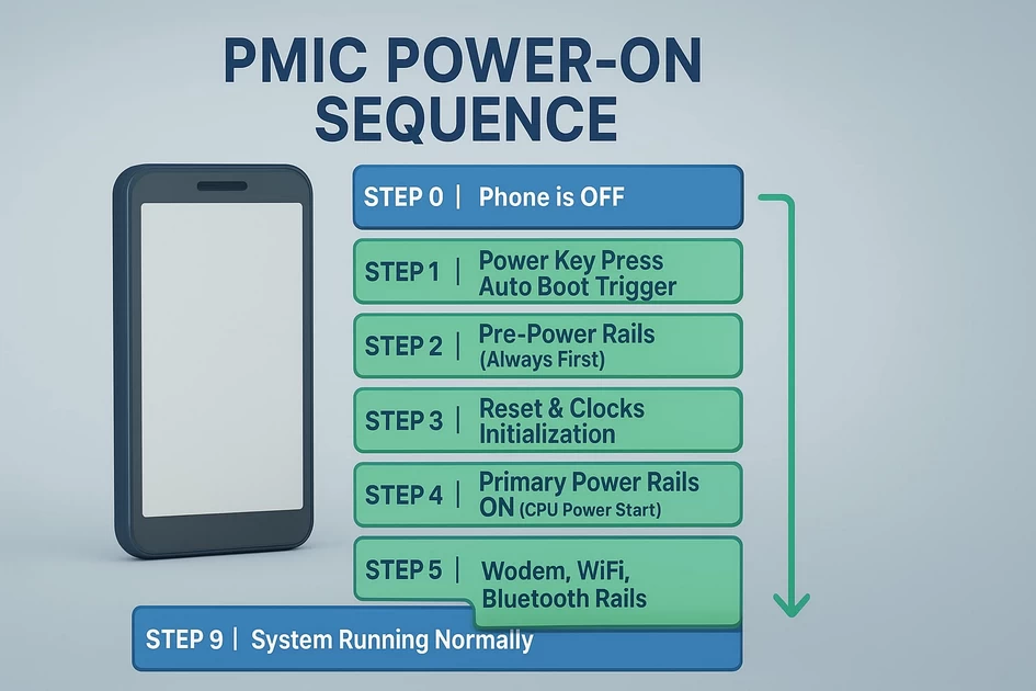
This is the actual boot sequence a phone follows from 0V to CPU running.
⭐ STEP 0 → Phone is OFF (Standby State)
- Only RTC LDO (Real-Time Clock) is ON
- PMIC monitors:
- Power key line (PWRKEY)
- USB VBUS (charging cable)
- Battery voltage
- Thermistor (NTC)
- All main rails are OFF
- CPU is in reset state
⭐ STEP 1 → Power Key Press / Auto Boot Trigger
Trigger signals that can start the phone:
- PWRKEY pressed
- USB charger inserted
- Battery plugged in (auto-boot devices)
PMIC detects one of these and enters BOOT INIT MODE.
⭐ STEP 2 → Pre-Power Rails (Always First)
PMIC brings up the basic rails required to “wake” the CPU.
Pre-power rails:
- VRTC / VPH_PWR – RTC domain
- VDD_MAIN – main battery line distributed everywhere
- PMIC internal regulators ON
If any of these rails fail → phone dead / no reaction.
⭐ STEP 3 → Reset & Clocks Initialization
PMIC signals:
- PS_HOLD low
- PMIC_RESET_N low
- BOOT_CONFIG pins read
- Xtal oscillator starts (19.2 MHz typical)
This provides the CPU with basic timing.
If PMIC_RESET_N never goes high → device cannot boot.
⭐ STEP 4 → Primary Power Rails ON (CPU Power Start)
PMIC now turns ON the essential CPU rails.
Qualcomm Primary rails:
- VDD_MX – internal logic domain
- VDD_CX – CPU core voltage
- VDD_PX / MDM rail – modem block
- VDD_GFX – GPU rail
- VDD_S1/S2 – sub power rails
If any rail is missing →
✔ 0.05–0.1A hang on DC supply
✔ no boot / no vibration
⭐ STEP 5 → Secondary Rails ON (Memory & Interfaces)
When primary rails stabilize:
PMIC enables:
- VDDQ – RAM I/O
- VDD1 / VDD2 – LPDDR supply
- VDD_SDIO – SD / eMMC I/O
- VDD_USB – USB transceivers
- VREG_Lxx – multiple LDO rails
If RAM rails fail → 0.2–0.3A current hang
If VDDQ missing → boot loop or stuck logo
⭐ STEP 6 → eMMC / UFS Storage Rails ON
Now the PMIC powers the storage chip.
For eMMC:
- VCC (2.8/3.0V) – NAND core
- VCCQ (1.8V/1.2V) – I/O interface
- RST_N toggles
- CMD/CLK/DATA lines active
For UFS:
- VCC (2.8/3.0V)
- VCCQ (1.2V/1.8V)
- REFCLK supplied
- RESET_N toggles
If these do not come up →
❌ dead storage, PMIC fault, or short
❌ 0.06A hang (Qualcomm common symptom)
⭐ STEP 7 → Modem, WiFi, Bluetooth Rails
PMIC now brings up:
- RF_Power rails
- WTR / RFFE rails (modem)
- WCN rails (WiFi/Bluetooth/GPS)
Failure here →
Device boots OK but no network / no WiFi.
⭐ STEP 8 → Display, Touch, Camera, Audio Rails
Finally, PMIC enables:
- Backlight boost (VBAT to 5–20V)
- Display LDO
- Touch IC I2C power
- Camera AVDD / DVDD / IOVDD
- Audio codec rails
If these fail →
- No display
- No backlight
- No touch
- No camera
- No audio
⭐ STEP 9 → PS_HOLD from CPU (Very Important)
CPU sends PS_HOLD HIGH to PMIC.
This tells the PMIC:
“I am alive, keep giving me power.”
If PS_HOLD fails:
✔ Phone boots for 0.5 sec → dies
✔ Classic blink issue
✔ Classic 0.15–0.25A drop
⭐ STEP 10 → System Running Normally
All regulators ON
Device running Android
Charging monitors active
Thermal system active
This is the full power-on ecosystem.
🔥 COMPLETE RAIL ACTIVATION TIMELINE (IMPORTANT)
1️⃣ VRTC / VPH_PWR
2️⃣ VDD_MAIN
3️⃣ PMIC_RESET_N
4️⃣ Clock (Xtal)
5️⃣ VDD_MX / VDD_CX (CPU)
6️⃣ VDDQ / VDD1 / VDD2 (RAM)
7️⃣ VCC / VCCQ (eMMC/UFS)
8️⃣ MODEM / RF Rails
9️⃣ Display / Touch rails
🔟 PS_HOLD High (CPU OK)-
byBIT
-
December 5, 2025
You May Also Like

-
Jan 30, 2026
mobile phone storage upgrade tips In 2026, our smartphones are more capable than ever, but higher-resolution photos and heavier...

-
Jan 27, 2026
In a twist for a technology many of us assumed would only ever get cheaper, solid-state drives (SSDs) and other...

-
Dec 11, 2025
Here is a complete, technician-level troubleshooting guide for ASUS H310M-E motherboard restarting while working (random restart, no blue screen). ✅...

-
Dec 9, 2025
How to Read RAW Dump From Chip-Off Extraction (Full Step-by-Step Guide) How to Read RAW Dump From Chip-Off Extraction 📌...
Sign up to receive our latest updates
Get in touch
Address
152A, Annavalaivu, Thuvakudimalai, Tiruchirappalli, Tamil Nadu – 620 022
Landmark : Near Post Office
Landmark : Near Post Office
bloomingtutorial@gmail.com