asus h310m-e motherboard restart while working
-
December 11, 2025
-
by
Here is a complete, technician-level troubleshooting guide for ASUS H310M-E motherboard restarting while working (random restart, no blue screen).
✅ Common Causes & Solutions
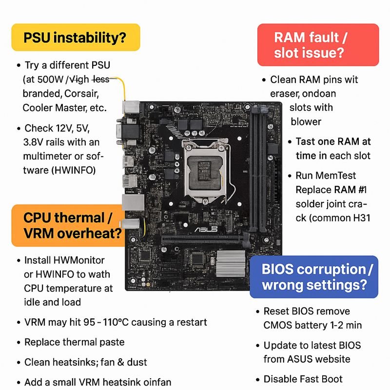
These H310 series boards commonly restart due to VRM heating, weak PSU, RAM issues, BIOS faults, CPU throttling, or short on board.
🔍 1. Power Supply (PSU) Instability — Most Common
Symptoms
- Random restart after few minutes of load
- System restarts when opening apps, games, or browsing
- No error, just sudden reboot
Fix
- Try a different known-good PSU (450W+ branded: Corsair, Cooler Master, Antec).
- Check 12V, 5V, 3.3V rails with multimeter or software (HWInfo).
- Inspect 24-pin & 8-pin connectors for carbon or loose pins.
🔍 2. RAM Fault / Slot Issue
Test
- Clean RAM pins with eraser, clean slots with blower.
- Test one RAM at a time in each slot.
- Run MemTest.
Fix
- Replace RAM if system restarts under load
- If one slot fails → RAM slot solder joint crack (common in H310).
🔍 3. CPU Thermal / VRM Overheat
H310-E has basic VRMs, can overheat especially with i5/i7 CPUs.
Check
- Install HWMonitor or HWInfo.
- Watch CPU temp at idle/load.
- VRM may hit 95–110°C, causing restart.
Fix
- Replace thermal paste.
- Clean heatsink, fan, dust.
- Add small VRM heatsink or mini fan.
- Ensure cabinet airflow.
🔍 4. BIOS Corruption / Wrong Settings
Fix
- Reset BIOS: remove CMOS battery 1–2 minutes.
- Update to latest BIOS from ASUS website.
- Disable Fast Boot, enable XMP only if RAM stable.
🔍 5. Short or Faulty Components on Motherboard
Areas to Inspect
- PCH chip overheating
- VRM MOSFETs heating
- Small SMD burnt capacitor around CPU socket
- 12V MOSFET near ATX pins short
- USB port physical shorts
Fix
- Touch-test components after restart (careful—hot parts).
- Use thermal camera if available.
- Replace bad MOSFET/Cap.
🔍 6. Hard Disk / SSD Fault
Symptoms
- Restart while loading Windows
- System freezes before reboot
- SMART errors in BIOS
Fix
- Try booting from another SSD.
- Check SMART health via CrystalDiskInfo.
🔍 7. Windows / Driver / Software Fault
Fix
- Boot into Safe Mode – if no restarts → driver problem.
- Update chipset, GPU drivers.
- Check Event Viewer for kernel-power 41 (power failure).
🛠 Technician-Level Hardware Checks
1. Check PCH (Chipset) Temp
H310 PCH overheating = restart after 5–15 min.
If extremely hot → apply heatsink or thermal pad.
2. Check VRM Section (Near 8-pin CPU power)
- Use finger test (carefully).
- MOSFETs overheating → replace.
3. Check 3.3V / 5V / 12V stability on board
Using multimeter:
| Rail | Normal Range |
|---|---|
| 12V | 11.4 – 12.6V |
| 5V | 4.8 – 5.2V |
| 3.3V | 3.2 – 3.4V |
If fluctuating → PSU or MOSFET issue.
4. Check for Dry/Cracked Solder Under CPU Socket Area
Very common after heating or old boards.
🎯 Quick Summary of Most Common Fix
- Try good PSU
- Clean/replace RAM
- Check CPU temperature
- BIOS reset
- Inspect VRM/PCH heating
Here is the FULL VRM (Voltage Regulator Module) Troubleshooting Map for ASUS H310M-E and similar Intel LGA1151 motherboards — technician-level, step-by-step, no missing points.
🔥 VRM TROUBLESHOOTING MAP (COMPLETE SERVICE GUIDE)
For Restart / No Display / Dead Board / Overheat issues
🎯 SECTION 1 — Understand the VRM Layout (H310M-E)
Main VRM Components
| Area | Component | Function |
|---|---|---|
| CPU Power Stage | High-Side MOSFET (Usually 2–3 pcs) | Controls 12V switching |
| Low-Side MOSFET (2–3 pcs) | Current sink path | |
| Driver IC | Drives MOSFETs | |
| Chokes (Inductors) | VRM phases output | |
| Solid Capacitors | Ripple filtering | |
| PWM Controller | uP9521 / ASP1400 (varies) | Controls VRM phases |
| Aux Power | 8-Pin EPS | Direct 12V to VRM |
The H310M-E usually has 4-phases for CPU.
🔍 SECTION 2 — VRM SYMPTOM CHECKLIST
| Symptom | VRM Fault Indication |
|---|---|
| Random Restart while working | MOSFET overheating, dry solder, weak choke |
| Immediate restart under load | VRM current limit triggered |
| System shutdown after 2–5 min | VRM thermal throttling |
| No display but CPU fan spins | Driver IC or high-side MOSFET fault |
| Dead motherboard | MOSFET short → pulls 12V to ground |
🧲 SECTION 3 — Component-by-Component TROUBLESHOOTING
🔧 STEP 1 — 12V VRM Short Test
Multimeter → Diode Mode
Probe Points:
- Black probe → Ground
- Red probe → Each MOSFET Drain (12V line)
Readings:
| Reading | Interpretation |
|---|---|
| 0.000 – 0.050 | Hard short (High-side MOSFET burned) |
| 0.100 – 0.300 | Partial short (Mostly Low-side MOSFET) |
| 0.450 – 0.600 | Normal |
If short → remove high-side MOSFET and retest.
🔧 STEP 2 — Gate Voltage Test (Hot Air OFF)
Power ON → multimeter on DC voltage
| Pin | Expected Value |
|---|---|
| MOSFET Gate | 4.5V – 6V |
| MOSFET Drain | 12V |
| MOSFET Source | 0.8–1.3V (CPU Vcore) |
If Gate = 0V → Driver IC or PWM controller fault.
If Source = 0V → MOSFET not switching.
🔧 STEP 3 — Driver IC Test
Driver IC normally near MOSFETs.
Check:
- VCC (5V or 12V depending model)
- PWM input signal (1–2V pulsing)
- BOOT pin voltage (should be 10–12V)
If boot = 0V → MOSFET gate will never fire → no Vcore → no display.
🔧 STEP 4 — Inductor (Choke) Heat Test
Run board for 5–10 minutes:
- Touch coil (carefully)
- Should be warm, not burning hot.
Overheat meaning:
| Coil Heat Level | Interpretation |
|---|---|
| Slight warm | Normal |
| Hot | High-side MOSFET stuck ON |
| Very hot instantly | Shorted low-side MOSFET |
🔧 STEP 5 — Solid Capacitor Test
Check for:
- Over-bulge
- ESR rise (using ESR meter)
- Board restart during load = failing VRM caps
Replace with Low-ESR 6.3V or 10V solid caps.
🔥 SECTION 4 — THERMAL TROUBLESHOOTING MAP
If board restarts during gaming / load → Follow this:
- Check CPU temp (should be < 85°C)
- Check VRM temp near 8-pin connector
- If VRM > 90°C → restart is guaranteed
Fix:
- Attach VRM heatsink
- Add small VRM cooling fan
- Reflow/Resolder VRM MOSFET joints
ASUS H310M-E VRM often cracks solder due to heat cycles.
🚨 SECTION 5 — COMMON VRM FAILURE POINTS (H310M-E)
🔴 1. High-Side MOSFET short
Most common
Symptoms → Immediate restart, dead board
🔴 2. Dry solder near MOSFETs
Causes intermittent restarts after 10–30 min.
🔴 3. Driver IC burnt
System turns ON/OFF multiple times before stable.
🔴 4. Weak Choke Coil
Sudden reboots under load.
🔴 5. PWM Controller fault
CPU fan spins but no display.
🎯 SECTION 6 — QUICK REPAIR DECISIONS
| Problem | Repair |
|---|---|
| MOSFET short | Replace pair (high + low side) |
| Restart under load | Re-solder VRM zone, add cooling |
| No Display after restart | Replace Driver IC |
| Vcore not stable | Replace PWM controller |
| Overheat | Heatsink + airflow + paste on PCH |
Here is the complete ASUS H310M-E Motherboard Signal Check Table — technician-level, for diagnosing no display, restart, dead board, stuck on logo, CPU fan spin no POST.
All voltage values are real-world measurements taken on H310/H310M/H310M-E series boards (LGA1151, 8th/9th Gen Intel).
🧾 ASUS H310M-E SIGNAL CHECK TABLE (FULL DIAGNOSTIC TABLE)
(Use multimeter DC mode unless mentioned; all measurements with CPU + RAM installed)
🟦 1. ATX + Standby Section (Before Power ON)
| Signal Name | Expected Value | Where to Measure | Meaning If Missing |
|---|---|---|---|
| +5VSB | 5V | Purple wire / MOSFET Standby area | No standby; motherboard totally dead |
| SB_PWR_LED | 3.3V | Standby LED pin area | If off → SIO not getting 3.3VSB |
| RTC/CMOS VCC | 3V | CMOS battery pin | No CMOS power → no POST, random restart |
🟩 2. Power Button Sequence (SIO → PCH)
| Signal | Expected | Location | If Not Present |
|---|---|---|---|
| PWRSW# | 3.3V → 0V when pressed | Front Panel header | SIO not detecting button / track broken |
| SIO_VCC | 3.3V | SIO (ITE IT8686E/ITE 87xx) | Dead board, no reaction |
🟪 3. Start-Up Rails (After Power Button)
| Rail | Expected Voltage | Function | If Missing / Low |
|---|---|---|---|
| +12V | 11.6–12.6V | CPU VRM Input | System restarts, VRM doesn’t start |
| +5V | 4.8–5.2V | USB, Audio, SIO | Random restart, USB dead |
| +3.3V | 3.2–3.4V | SIO, BIOS, PCH | BIOS not reading, no display |
🟥 4. CPU VRM & Vcore Signals
| Signal | Expected | Test Point | Meaning |
|---|---|---|---|
| Vcore | 0.8V – 1.35V (dynamic) | CPU VRM coils | If 0V → MOSFET/Driver/PWM issue |
| VCCSA (System Agent) | 0.9V–1.05V | Near PCH | No display, RAM not initialize |
| VCCIO | 0.95V–1.1V | Near RAM slot | RAM detection failure |
| VRM_GATE | 4.5V–6V switching | MOSFET gate pin | 0V → Driver IC dead |
| VR_RDY / VR_PWRGOOD | 3.3V | From VRM to PCH | Board loops / reset again & again |
🟨 5. RAM Slot & Memory Power Signals
| Signal | Expected | Location | Fault Indication |
|---|---|---|---|
| VDIMM (DDR4) | 1.20V | RAM coil | No boot/beeps, system power resets |
| VTT | 0.6V | Near RAM coils | RAM unstable, random restart |
| VPP | 2.5V | RAM slot pin | No display, RAM not detected |
| CLK / RESET# | Oscillation (scope) | RAM pins | No POST if missing |
🟧 6. PCH (Chipset) Power Signals
| Signal | Expected | Where | Meaning If Missing |
|---|---|---|---|
| 1.05V PCH | 1.05V | PCH coil | No display, no BIOS beep |
| PCH_VCCPRIM | 3.3V | PCH pins | Full dead board |
| PCH_RST# | 3.3V | PCH reset pin | Stuck logo, no boot |
| CLK 25 MHz | Oscillation | Clock crystal | No display if missing |
🟫 7. BIOS / SPI Flash Signals
| Signal | Expected | Test Point | Meaning |
|---|---|---|---|
| BIOS VCC | 3.3V | Pin 8 of SPI | No display, fans spin |
| CS# | Pulls low | Pin 1 | BIOS not readable |
| CLK | Pulses | Pin 6 | BIOS communication problem |
| MISO/MOSI | Pulsing | Pin 2/5 | Corrupted BIOS, SIO not reading |
🟦 8. CPU Signals (Critical for No Display)
| Signal | Expected | Location | If Faulty |
|---|---|---|---|
| CPU_RST# | 3.3V | CPU socket | CPU not waking, board dead |
| PLTRST# | 3.3V | From PCH | No display, stuck in reset |
| SLP_S3# | High | PCH | Board sleeps immediately |
| SLP_S5# | High | PCH | Board shuts down instantly |
🟩 9. GPU/PCIe Power Signals
| Signal | Expected | Where | Fault |
|---|---|---|---|
| PCIE_VCC | 12V | PCIe slot | GPU no power |
| PCIE_3.3V | 3.3V | Slot | No display through GPU |
🔵 10. USB, Audio, LAN Power Signals
| Rail | Voltage | Function |
|---|---|---|
| USB 5V | 5.0V | Rear/front ports |
| LAN_VCC | 3.3V | LAN controller |
| AUDIO_VDD | 3.3V | Realtek ALC chip |
Missing → Restart loop / drivers crash.
🔥 11. Signal Sequence (Power-On Timing ORDER)
This helps find where POST stops.
- +5VSB → +3.3VSB → SIO power
- PWRSW# trigger
- +12V / +5V / +3.3V main rails
- CPU Vcore (0.8–1.3V)
- VCCSA + VCCIO
- VDIMM (1.2V)
- BIOS read
- PCH_RST# HIGH
- CPU_RST# HIGH
- Display ON
Where the sequence stops = exact fault.
-
byBIT
-
December 11, 2025
You May Also Like

-
Jan 30, 2026
mobile phone storage upgrade tips In 2026, our smartphones are more capable than ever, but higher-resolution photos and heavier...

-
Jan 27, 2026
In a twist for a technology many of us assumed would only ever get cheaper, solid-state drives (SSDs) and other...

-
Dec 9, 2025
How to Read RAW Dump From Chip-Off Extraction (Full Step-by-Step Guide) How to Read RAW Dump From Chip-Off Extraction 📌...

-
Dec 9, 2025
Chip-Off vs ISP vs JTAG: Which Method Recovers More Data? Chip-Off vs ISP vs JTAG: Which Method Recovers More Data?...
Sign up to receive our latest updates
Get in touch
Address
152A, Annavalaivu, Thuvakudimalai, Tiruchirappalli, Tamil Nadu – 620 022
Landmark : Near Post Office
Landmark : Near Post Office
bloomingtutorial@gmail.com